
Want to put on some nice indeglo gauges, but don’t want to have inaccurate gauge readings afterwards? Not comfortable doing the “take a picture of your gauges before and make them kinda look the same afterwards method”? This how-to will show you how to re-calibrate your needles in your gauge cluster to 100% accuracy after removing the needles for a gauge face install, without buying those expensive re-calibrators. This how-to assumes that you already know how to remove the gauges from the car (you would have had to remove them to replace the gauges, right?). This how-to is known to work on the 1999-2004 V6, GT, Bullit, and Mach 1 gauge clusters. They will not work on the 1994-1998 SN95, as the motors for the cluster are different.
In a nutshell, what we need to do is to add a small amount of voltage to the back of the motors of your needles. You can go about adding that voltage a bunch of different ways, and the different amount of volts will work. We have tested between 5 volts and 15 volts with the same result. One way would be to use a cigarette lighter plug and attach some wires to it with alligator clips. Another would be to splice in the alligator clips to an A/C to D/C adaptor that everyone seems to have lying around the house for old RC cars that they don’t have anymore. But for this how-to, we chose a 9V battery with a few test leads from Radio Shack attached to them. They’re only a few bucks. You will need a total of 4 leads, with 2 positive and 2 negative. The kit, located here (RadioShack® 30" (76.2cm) Test/Jumper Leads - RadioShack.com), comes with all the leads you would need.
Materials needed:
-Screwdriver with a torx T15 bit
-2 wires with alligator leads
-9V battery
-A beer (optional, of course)
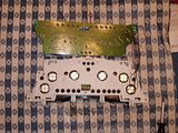
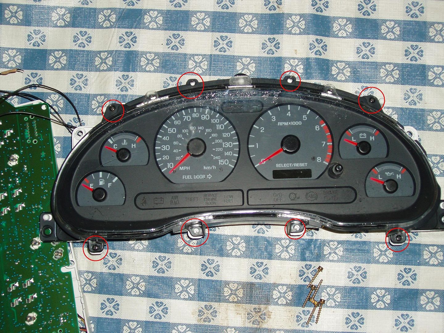
Step 1: With the gauge cluster fully removed from the car, flip the gauge cluster on its face. There are 6 Torx T15 bolts that hold the back on the cluster. Remove them and remove the rear panel.
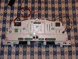
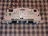
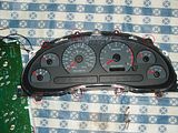
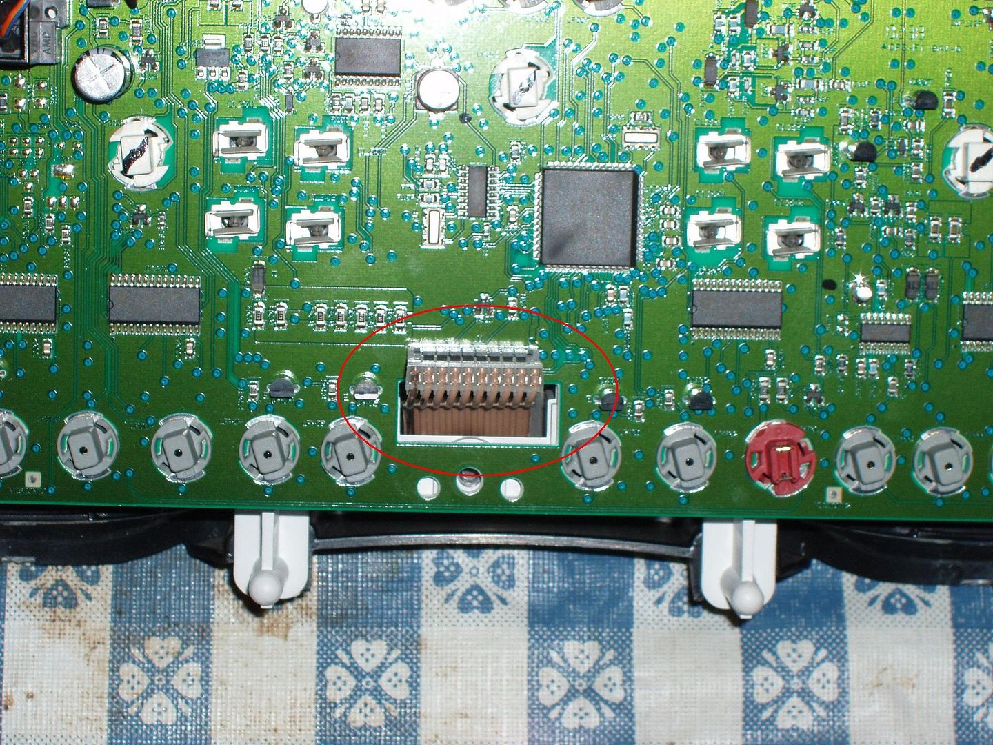
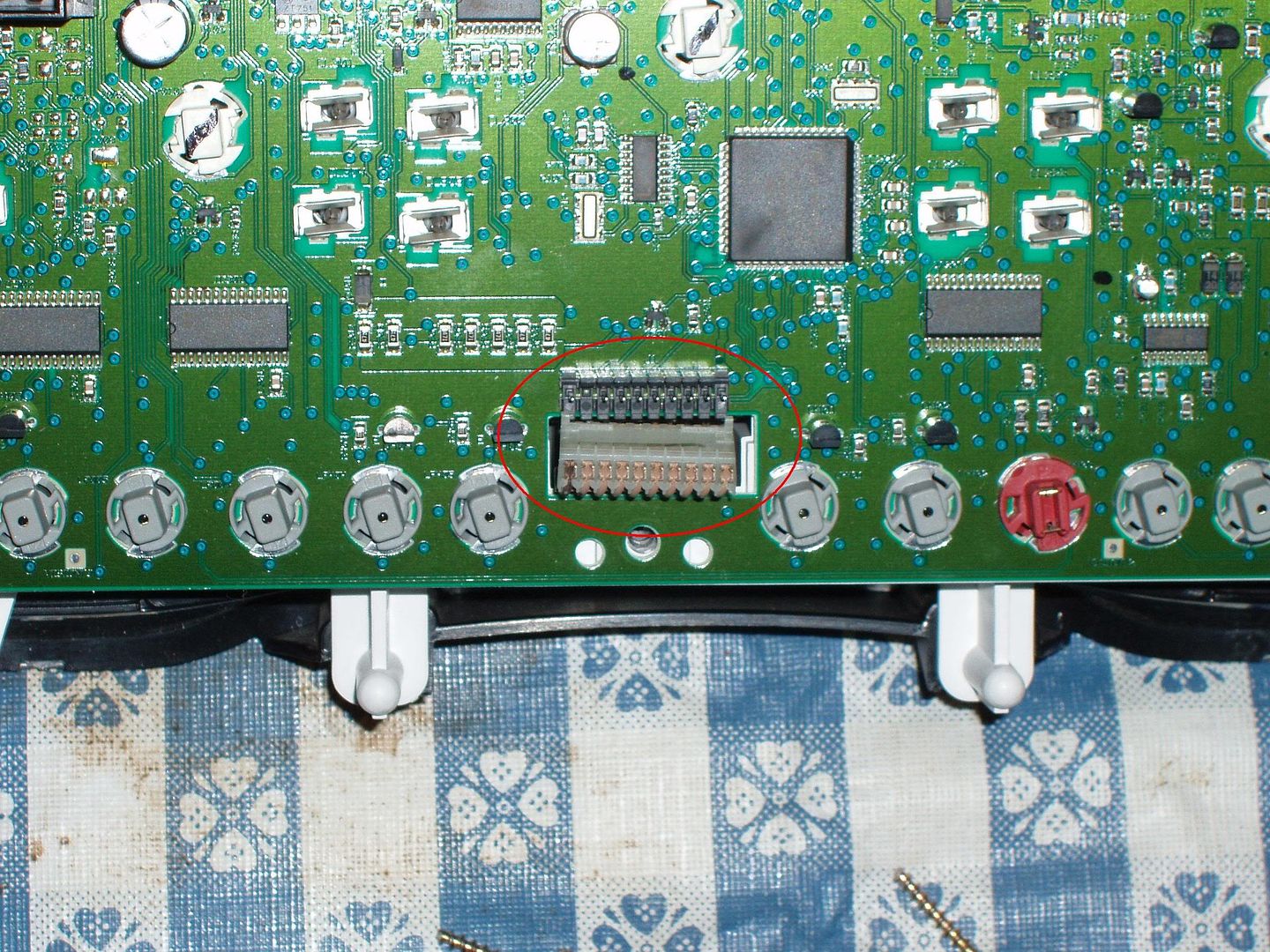
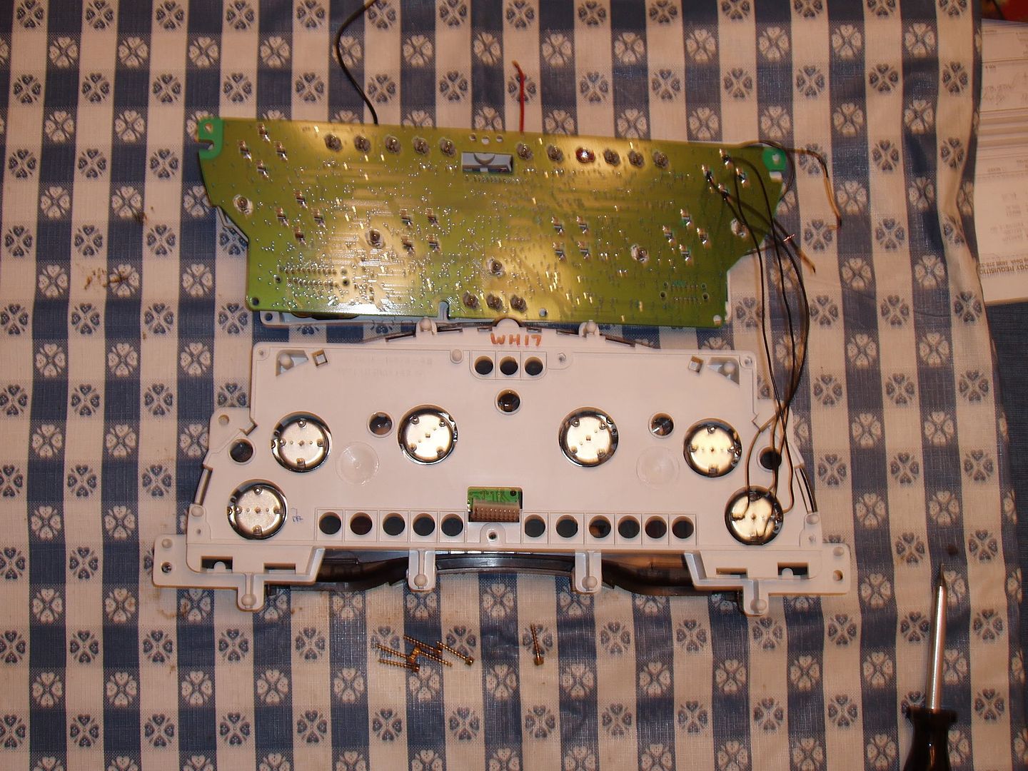
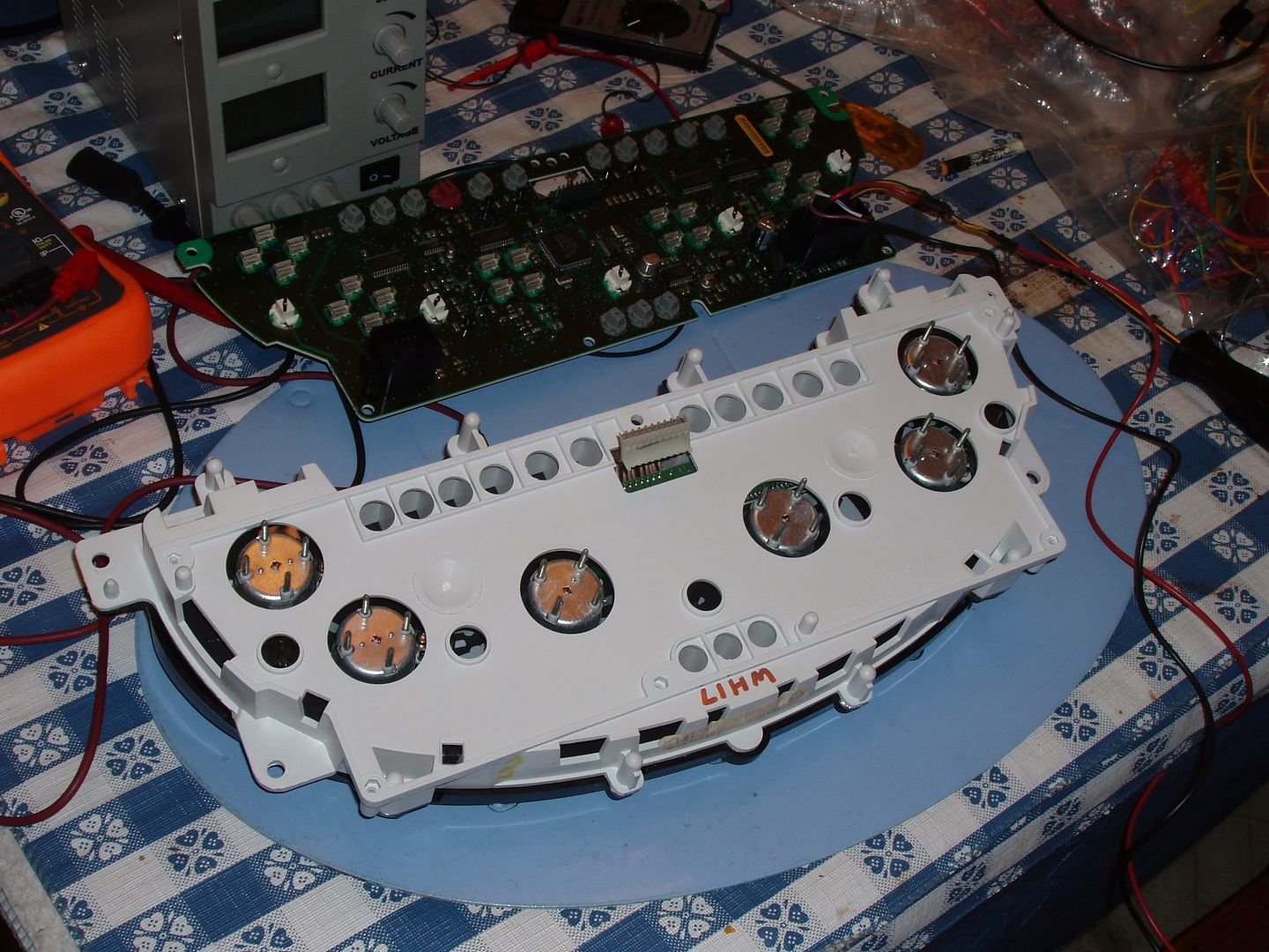
Step 2: On the back of the cluster there is a plug that holds the PCB board in place. Un-plug that pin from the board, being very careful not to break it. Break the plug and your gauge cluster is toast. Once you have the plug un-plugged from the PCB board, remove the board and set it aside.

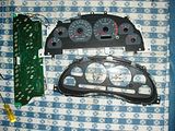
Step 3: Flip the gauge cluster back over and remove the front of the gauge cluster. The same 6 bolts that held the back on are the same 8 that hold the front gauge bezel on. Once the screws are removed, set the front gauge bezel aside. Using either your finger or a simple kitchen fork, remove all 6 needles from the gauges and set them aside.
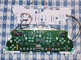
Step 3: Flip the gauge cluster back over, being careful not to harm the now exposed needles on the front of the cluster. On the back of each needle motor, there are 4 prongs.
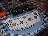
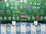
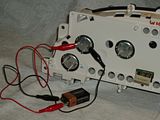
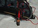
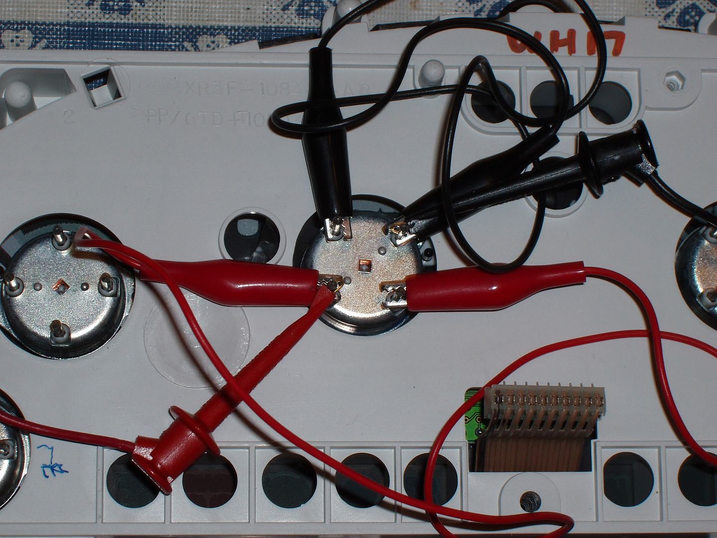
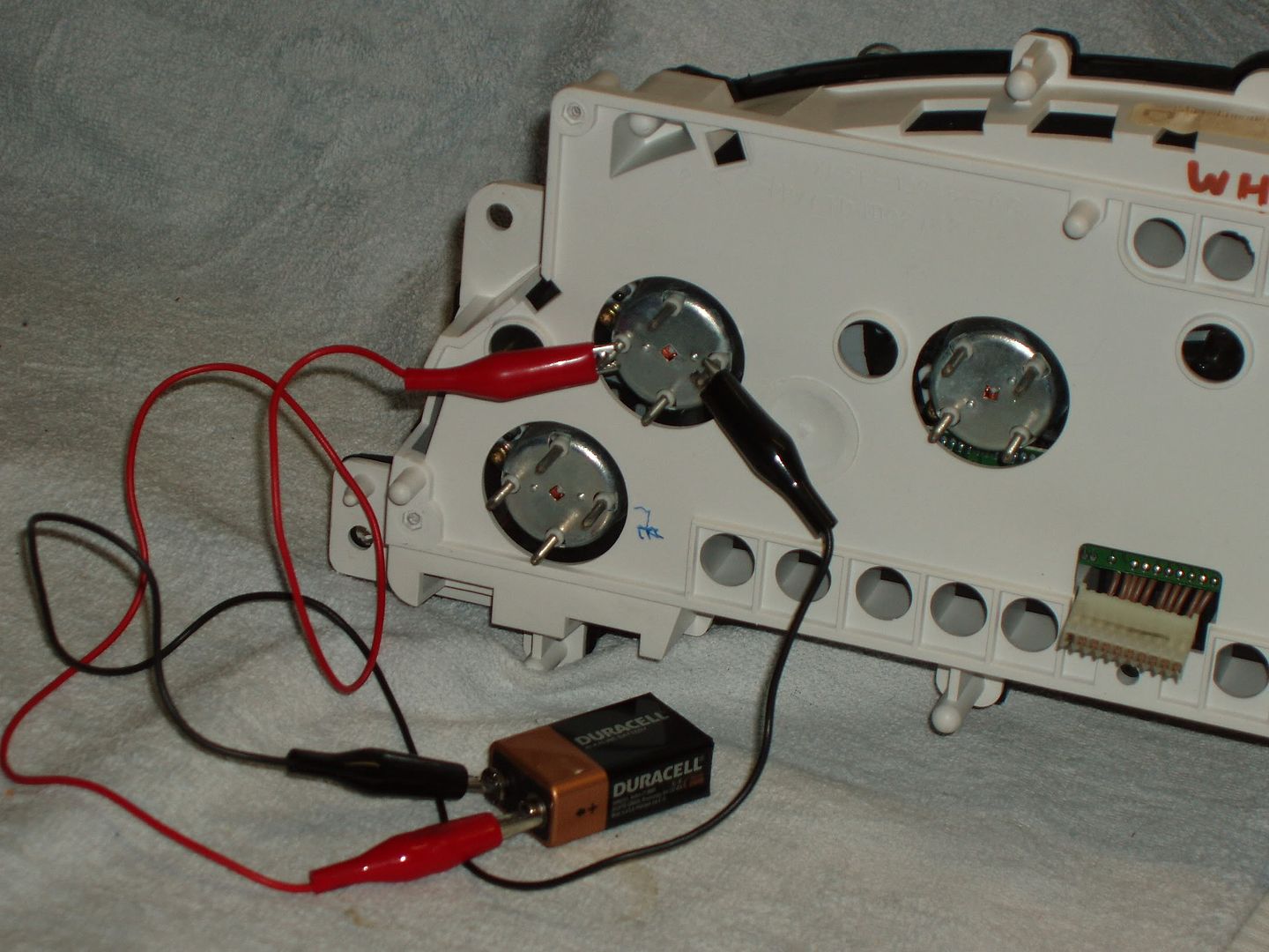
What you need to do is apply voltage to those 4 prongs for the speedo and tach, and the left and right prongs for the 4 smaller needle motors (the top and bottom prongs for those needles are not used). Attach 2 positive and 2 negative leads to the positive and negative leads on the 9V battery, then attach them to the back of the needle motors like in the pictures below, with the top of the gauge cluster facing upwards.
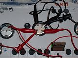
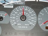
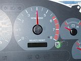
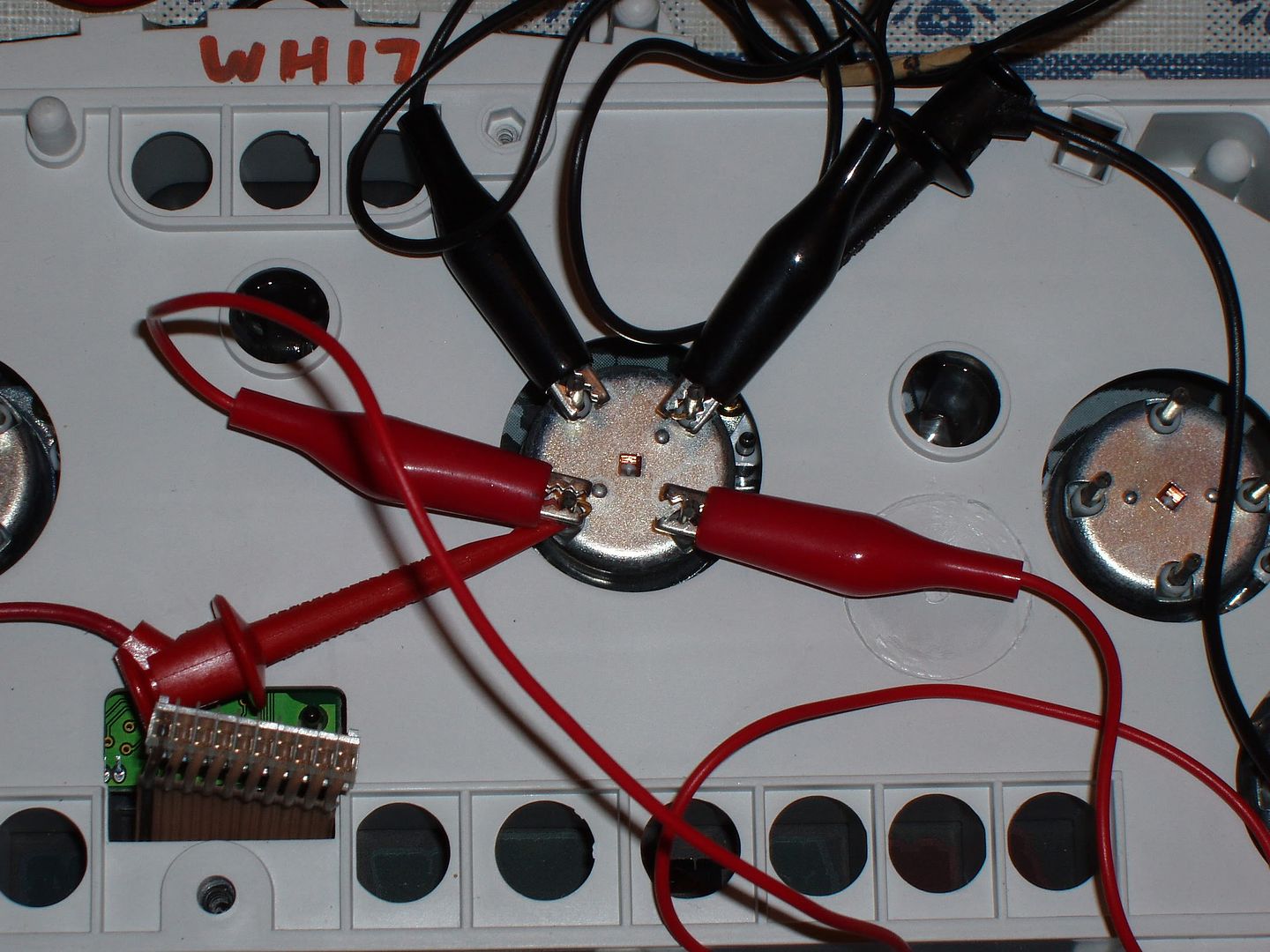
Step 4: Apply the power leads from the battery to the pins on the back of the tach or speedo motor (whichever you want to do first) as you see them in the pics above. With voltage applied to the needle motor, the needle pin will shoot to the top dead center position, so you know at what position to put the needle back on at. Take the 2 larger needles and leave the 4 smaller ones. For the tach, put the needle at exactly 4,000 RPMs. For a speedometer with a 150 MPH max, put the needle at exactly 80 MPH. When you put the needle on and take your finger off, if the needle moves slightly to the left or right, take it off and try again until the needle is exactly in those spots. Don’t press down all the way, or the needle will rub on the gauge face and your needle will jump around. But don’t leave it up too high either, or light will shine through and the needle won’t be bright at night.
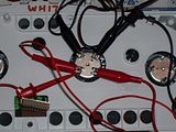
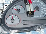
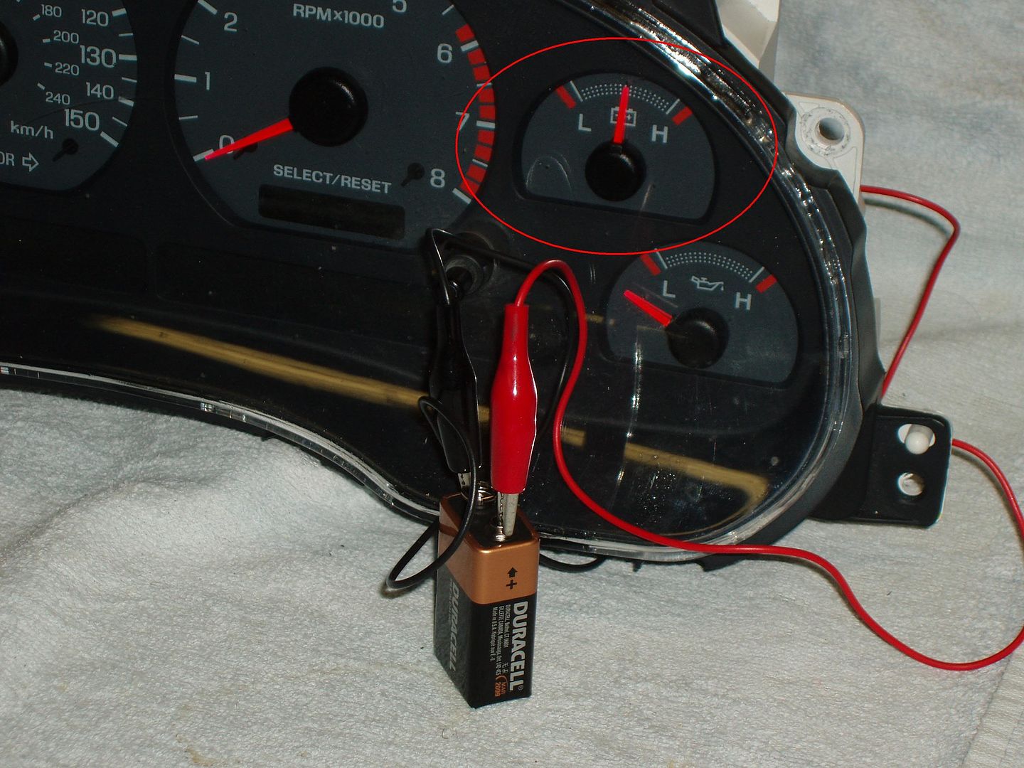
Step 5: Now we’re going to do the 4 smaller gauges. For the smaller needles, the prongs are in a diamond formation. The positive terminal is the left prong and the negative is the right prong. The top and bottom prongs for the smaller needle motors are not used, so you will only need 2 lead wires for these, as opposed to the 4 for above. If you want, you can still use the 4 lead wires, and hook them up to 2 needle motors at a time, your call. Do the exact same procedure for the smaller needles that you did in step 4 for the larger needles. Place all the needles in the exact top center position when you have the power supplied to that needle motor.
Step 6: Double check to make sure that all the needles are fully calibrated before putting everything back together. After all gauges have been calibrated, putting everything back together is just the reverse of normal. Flip the gauges over to the back and put the PCB board back on. Plug the connector in, then put the back of the gauge cluster on, making sure the screws are tight. Flip the cluster over and re-install the front of the cluster, making sure those screws are tight as well. After everything is re-installed, put the cluster back into the car. All the needles should be just as accurate as the day your car rolled off the assembly line.
Credits:
Write-up was written by IRSmart of www.Corral.net and www.Mustangworld.com. All pictures taken by markolson of www.Corral.net and used with his consent. Method was accidentally found by markolson when he was testing out methods of making the oil pressure gauge useful. My gauge cluster, his tests, his pictures, and my realization of what he had accidentally discovered made this how-to possible. Written on 4/13/09.
In a nutshell, what we need to do is to add a small amount of voltage to the back of the motors of your needles. You can go about adding that voltage a bunch of different ways, and the different amount of volts will work. We have tested between 5 volts and 15 volts with the same result. One way would be to use a cigarette lighter plug and attach some wires to it with alligator clips. Another would be to splice in the alligator clips to an A/C to D/C adaptor that everyone seems to have lying around the house for old RC cars that they don’t have anymore. But for this how-to, we chose a 9V battery with a few test leads from Radio Shack attached to them. They’re only a few bucks. You will need a total of 4 leads, with 2 positive and 2 negative. The kit, located here (RadioShack® 30" (76.2cm) Test/Jumper Leads - RadioShack.com), comes with all the leads you would need.
Materials needed:
-Screwdriver with a torx T15 bit
-2 wires with alligator leads
-9V battery
-A beer (optional, of course)
Step 1: With the gauge cluster fully removed from the car, flip the gauge cluster on its face. There are 6 Torx T15 bolts that hold the back on the cluster. Remove them and remove the rear panel.


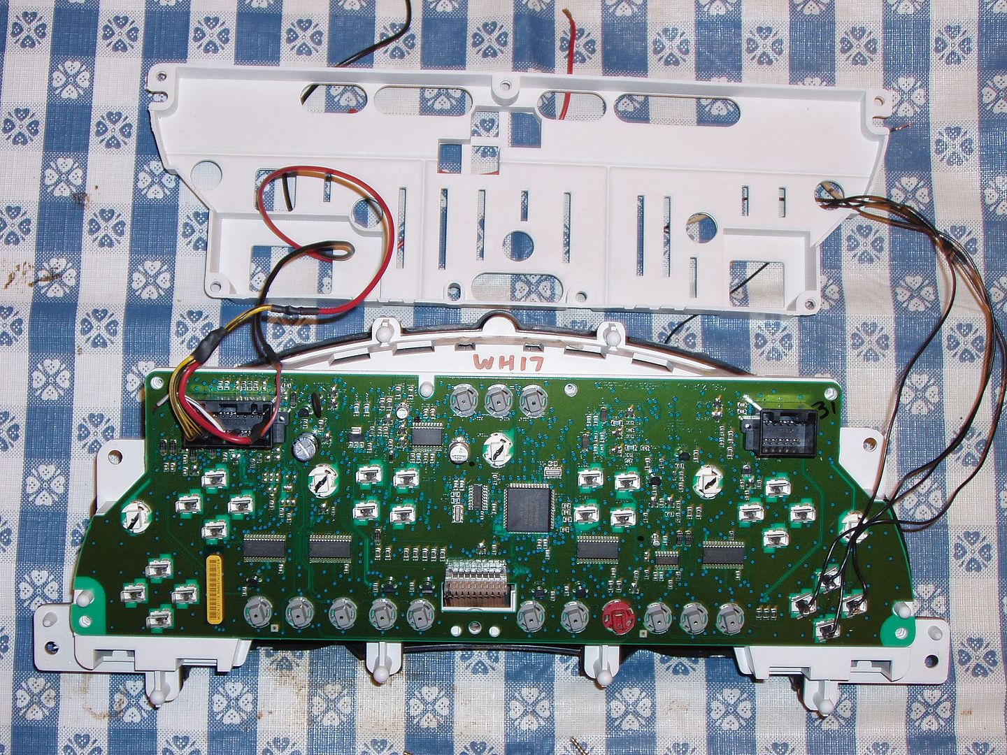
Step 2: On the back of the cluster there is a plug that holds the PCB board in place. Un-plug that pin from the board, being very careful not to break it. Break the plug and your gauge cluster is toast. Once you have the plug un-plugged from the PCB board, remove the board and set it aside.
Step 3: Flip the gauge cluster back over and remove the front of the gauge cluster. The same 6 bolts that held the back on are the same 8 that hold the front gauge bezel on. Once the screws are removed, set the front gauge bezel aside. Using either your finger or a simple kitchen fork, remove all 6 needles from the gauges and set them aside.

Step 3: Flip the gauge cluster back over, being careful not to harm the now exposed needles on the front of the cluster. On the back of each needle motor, there are 4 prongs.
What you need to do is apply voltage to those 4 prongs for the speedo and tach, and the left and right prongs for the 4 smaller needle motors (the top and bottom prongs for those needles are not used). Attach 2 positive and 2 negative leads to the positive and negative leads on the 9V battery, then attach them to the back of the needle motors like in the pictures below, with the top of the gauge cluster facing upwards.
Step 4: Apply the power leads from the battery to the pins on the back of the tach or speedo motor (whichever you want to do first) as you see them in the pics above. With voltage applied to the needle motor, the needle pin will shoot to the top dead center position, so you know at what position to put the needle back on at. Take the 2 larger needles and leave the 4 smaller ones. For the tach, put the needle at exactly 4,000 RPMs. For a speedometer with a 150 MPH max, put the needle at exactly 80 MPH. When you put the needle on and take your finger off, if the needle moves slightly to the left or right, take it off and try again until the needle is exactly in those spots. Don’t press down all the way, or the needle will rub on the gauge face and your needle will jump around. But don’t leave it up too high either, or light will shine through and the needle won’t be bright at night.

Step 5: Now we’re going to do the 4 smaller gauges. For the smaller needles, the prongs are in a diamond formation. The positive terminal is the left prong and the negative is the right prong. The top and bottom prongs for the smaller needle motors are not used, so you will only need 2 lead wires for these, as opposed to the 4 for above. If you want, you can still use the 4 lead wires, and hook them up to 2 needle motors at a time, your call. Do the exact same procedure for the smaller needles that you did in step 4 for the larger needles. Place all the needles in the exact top center position when you have the power supplied to that needle motor.

Step 6: Double check to make sure that all the needles are fully calibrated before putting everything back together. After all gauges have been calibrated, putting everything back together is just the reverse of normal. Flip the gauges over to the back and put the PCB board back on. Plug the connector in, then put the back of the gauge cluster on, making sure the screws are tight. Flip the cluster over and re-install the front of the cluster, making sure those screws are tight as well. After everything is re-installed, put the cluster back into the car. All the needles should be just as accurate as the day your car rolled off the assembly line.
Credits:
Write-up was written by IRSmart of www.Corral.net and www.Mustangworld.com. All pictures taken by markolson of www.Corral.net and used with his consent. Method was accidentally found by markolson when he was testing out methods of making the oil pressure gauge useful. My gauge cluster, his tests, his pictures, and my realization of what he had accidentally discovered made this how-to possible. Written on 4/13/09.
Last edited:

